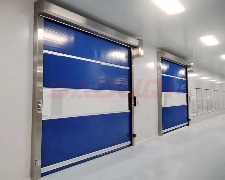
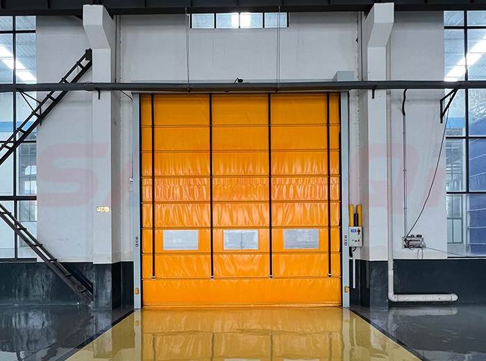
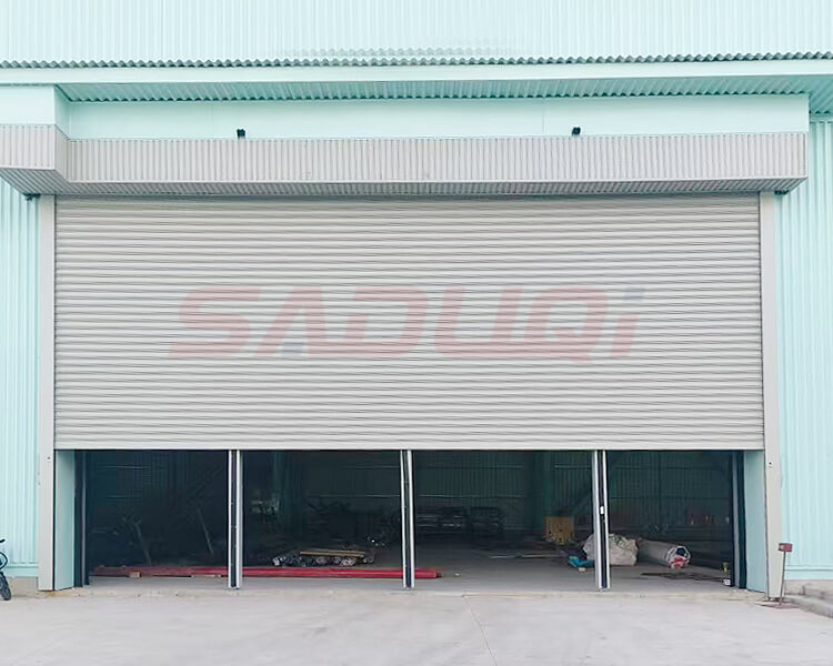
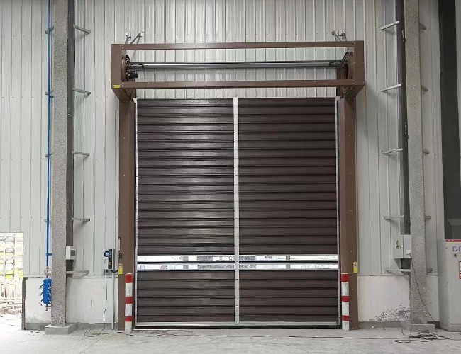
Installation Guide for Rigid Turbine High Speed Doors
Blog 2026-09-18
Rigid high-speed doors are heavier, operate at high speeds and rely on a worm gear drive and spring balancing system. Installation accuracy directly determines their service life, operational stability and safety performance; any installation deviations can lead to a range of faults, including abnormal noises, jamming, panels falling off, motor burnout and safety failures.
Preparations Prior to Installation
On-site Survey and Opening Verification
Measure the clear dimensions of the door opening: width W × height H. Check against the dimensions specified in the order; if the deviation exceeds 10 mm, the wall must be prepared in advance.
Identify the installation method: inside the opening (within the wall), within the opening, or outside the opening (outside the wall). Mark the installation reference lines in advance.
Wall inspection: Concrete or solid brick walls are optimal; hollow brick or lightweight partition walls require pre-embedded steel plates for reinforcement; allow for an installation space of ≥150 mm on both sides of the door opening, and a space of ≥600 mm at the top to accommodate the height of the motor head.
Power supply confirmation: Dedicated single-phase 220V or three-phase 380V power supply for the door operator, with a dedicated residual current device (RCD); the power cable must be routed to the upper side of the door opening (2.2 m above the floor).
Floor clearance: The floor surface inside and outside the door opening must be level, free of standing water and debris; any floor recesses must be levelled in advance.
All Components
Side guide rails, turbine head assembly, motor + gearbox, aluminium alloy door panel blades, bottom beam, top cover guard plate, steel wire rope / torsion springs, limit switches, electrical control box, infrared safety light curtain, ground-mounted magnetic induction coil, push-button panel, expansion bolts, sealant, fixing brackets.
Guide Rail Frame
Use a chalk line to mark the vertical centre line of the door opening and the vertical reference lines for the guide rails on both sides; use a plumb bob to check the verticality.
Position the aluminium alloy guide rails on both sides, aligning them with the marked lines, ensuring the bottom rests flush against the floor; use a spirit level to check that the vertical deviation of the guide rails is ≤2 mm/m.
Secure the guide rails using expansion bolts and fixing brackets: drill holes in separate sections at the top and bottom, with a set of fixing points every 300 mm; For hollow-core walls, install pre-embedded steel plates for reinforcement.
Ensure the clear distance on the inner sides of the guide rails on both sides is uniform and that they are parallel to each other; measure and correct using diagonal measurements, ensuring the diagonal error is ≤3 mm.
Fit rubber impact-resistant sealing strips to the bottom of the guide rails, ensuring the gap between the bottom of the rails and the floor is controlled to ≤5 mm.
Fill the space on the outer side of the guide rails with foam sealant and apply weather-resistant sealant to the outer surface to prevent the ingress of dust and rainwater.
Lifting the Turbine Head
The crossbeam at the top of the doorway opening must be cleared and levelled, with no protruding obstacles; the load-bearing capacity of the crossbeam must be sufficient to support the weight of the spindle head.
Two people must work together to hoist the turbine spindle head into position, raising it to the centre of the doorway opening, with both ends of the spindle engaged in the top grooves of the guide rails on either side.
Use a spirit level to calibrate the horizontal alignment of the turbine main shaft, ensuring the left-right height difference is ≤1 mm; secure the head base using channel steel brackets and expansion bolts.
* Install the torque-balancing springs (turbine door balancing system):
One end of the spring is secured to the turbine head’s main shaft, whilst the other end is secured to the top load-bearing bracket;
Pre-tension the spring (fine-tune the pre-tension after the door panel has been fitted to prevent the panel from sagging);
Fit the spring protective cover to prevent the risk of fingers being trapped.
Connect the motor to the worm gearbox coupler, align the slots, lock the fixing pins in place, and confirm that the drive operates without misalignment or jamming.
Assembly of Door Panels and Bottom Beams
Lay out all the rigid aluminium alloy door panel slats on the floor and check that the slat surfaces are free from scratches, the clips are intact, and the sealing strips are complete.
Assemble the bottom beam: Snap the rubber anti-impact bottom strip into the bottom beam profile, and fit the side sliders to both ends of the bottom beam.
Hoist the bottom beam into place, insert the bottom beam sliders into the guide rail grooves on both sides, and secure it with temporary supports.
Install the turbine door panels in layers:
Snap the upper latch of the first door panel into the groove on the main shaft’s turbine disc and secure the latch;
Stack each panel upwards in sequence, ensuring sound-insulating sealing strips are fitted between the panels and that all panels are securely fastened with no play;
Provide temporary support every 3–5 panels to prevent the door panels’ own weight from pulling on the main shaft and causing deformation;
Once all high speed door panels have been installed, fine-tune the preload of the balancing springs: remove the temporary supports; the door panel should remain suspended at any height without sagging or moving automatically.
Fit the top decorative cover (motor housing cover), securing it with snap fasteners to conceal the turbine motor head, enhancing aesthetics and providing dust protection.
Installation of Safety Devices
Infrared Safety Light Curtain
The transmitter and receiver units of the light curtain are mounted at the lower-middle positions of the left and right guide rails respectively (300–800 mm above the floor);
Cables are routed along the inner side of the guide rails and secured with cable ties to prevent damage from friction with the door panel;
The cables are connected to the safety signal terminals in the electrical control box; should the light curtain be obstructed, the door will immediately stop descending and automatically reverse.
Ground-mounted Induction Loop
Cut a square channel into the ground on the outer side of the door opening, 5 cm deep, and lay the copper wire for the induction loop, winding it 6–8 times;
Seal the channel with bitumen or epoxy resin, and route the copper lead wires along the wall to the electrical control box;
Mount the induction loop controller next to the electrical control box and connect it to the corresponding signal port; the door will automatically rise when a vehicle drives over the loop.
Other Optional Accessories
Radar Sensor: Installed on the inside of the protective panel above the gate opening, aligned with the vehicle passage area;
Airbag at the Bottom Edge: A safety airbag is built into the bottom beam; the gate will rise immediately upon collision with an object;
Access Control Card Reader / Remote Control Receiver: Mounted on the side of the electrical control box.
Installation of the Electronic Control System
Fixed electrical control box: Installed on the side wall of the door opening at a height of 2.2 m for ease of operation and maintenance.
Wiring specifications: The main motor cables, light curtain cables, ground-sensor cables and push-button cables must be routed separately, protected by conduit, and kept separate from high- and low-voltage circuits.
Wiring sequence (refer to the control box wiring diagram):
1) Connect the external 220V power supply live, neutral and earth wires; the earth wire must be reliably earthed;
2) Connect the motor power wires (forward/reverse, limit switches);
3) Connect the upper and lower limit switch signal wires (upper limit, lower limit);
4) Connect the infrared safety light curtain signal wires;
5) Connect the wiring for the external push-button panel (Up / Down / Emergency Stop);
6) Connect signal wires for optional equipment such as remote controls, radar sensors and ground-mounted sensors;
Tighten all terminal connections, wrap exposed copper wires with insulating tape, and bundle any excess cables neatly inside the box.
Install emergency stop buttons: one on each side of the door opening to cut off power and stop the system in an emergency.
Travel Limit Adjustment
Switch on the main power supply and test the motor’s forward and reverse rotation in jog mode: press ‘Up’ to move the door panel upwards; press ‘Down’ to move the door panel downwards. To reverse the direction, swap the two power wires of the motor.
Set the lower limit switch:
Operate the door in jog mode downwards; once the bottom rail touches the ground, stop the operation and adjust the limit switch knob to lock the lower limit position; after the door closes, the gap at the bottom of the door panel should be ≤5 mm.
Setting the upper limit switch:
Operate the motor in jog mode to lower the door; stop when the door panel is fully rolled up and does not strike the head guard, then lock the upper limit switch; the fully open height of the doorway must be sufficient to allow vehicles to pass through.
Repeat the up and down cycle three times to confirm that the limit switches are accurate and that there is no over-travel or bottoming out.
Safety function test:
If the infrared light curtain is obstructed during descent, the door must immediately reverse;
If the bottom beam contacts an obstacle, the airbag or light curtain must trigger a reverse ascent;
Pressing the emergency stop button must instantly cut power to the entire unit and halt operation.
Door Operation
After 10 consecutive no-load lifts, the operation was smooth with no abnormal noises, jamming or vibration.
Balance test: When the door panel is held at any height, it does not slide down or rise automatically.
Speed meets specifications: The lifting speed of rigid roller-shutter doors is typically 0.6–1.2 m/s, in accordance with the order specifications.
All safety devices are operational: light curtains, airbags, emergency stop and floor sensors trigger correctly.
Sealing performance: Once closed, the door gap is airtight and light-tight.
All opening methods—remote control, manual buttons, radar and floor sensors—switch normally.
The motor shows no abnormal overheating, and there is no overheating of wiring or electrical leakage in the control box.
High-speed sectional doors operate by means of high-speed reciprocating rolling motion, with all components working in unison. The precision of installation determines the smoothness of operation; the robustness of the installation determines the service life of the equipment; and the correct installation of safety fittings determines operational safety. Proper installation is the fundamental prerequisite for the long-term, stable operation of the door.