Detailed Introduction to Electric Smoke Curtains
Blog 2026-08-19
Electric smoke curtains (retractable smoke curtains) are a core fire protection component of building smoke control and exhaust systems. Under normal conditions, they are fully retracted or folded away and concealed inside the ceiling cassette, so as not to interfere with interior finishes, natural lighting, or pedestrian traffic.
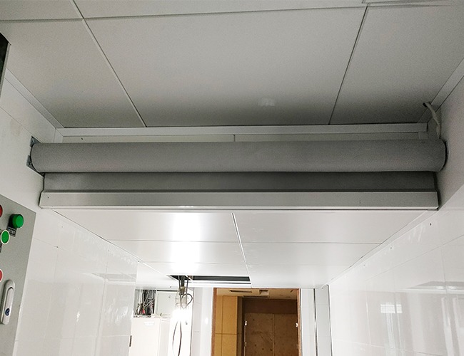
In the event of a fire, the electrically driven smoke curtain automatically lowers, forming a vertical smoke chamber that creates independent smoke compartments. This prevents the lateral spread of high-temperature smoke, containing it above the ceiling. Working in conjunction with smoke exhaust equipment to facilitate centralized smoke extraction, the system ensures smoke-free, clear headroom in the evacuation pathways below, thereby extending the time available for safe evacuation.
Electric Smoke Curtain Performance Parameters
1. Interlock response: Upon confirmation of a fire alarm, the control unit issues an interlock signal within 15 seconds, and the system fully lowers into position within 60 seconds.
2. Effective smoke barrier depth: Mechanical smoke extraction ≥ 10 per cent of the clear height and ≥ 500 mm; natural smoke extraction ≥ 20 per cent of the clear height and ≥ 500 mm.
3. Clear height from the floor to the bottom of the curtain upon full deployment: standard ≥2.0 m; minimum in areas with space constraints ≥1.7 m
4. Fire and smoke resistance: withstands 620°C for 30 minutes; smoke leakage rate ≤25 m³/(m²·h)
5. Power supply: Main power AC 220 V, control circuit DC 24 V; built-in backup battery capable of completing ≥3 full lowering cycles in the event of a power failure.
6. Temperature-controlled fallback mechanism: Standard 73°C fusible link; automatic release and lowering upon motor failure due to high temperature.
Electric Smoke Curtain Advantages
Concealed installation: Stored out of sight when not in use, without compromising the interior design
Four-mode control: Automatic interlocking, remote control from the control room, on-site manual operation, and self-lowering under its own weight in the event of a power cut
Status feedback: Independent upper and lower limit signals are transmitted to the fire alarm control panel, enabling real-time monitoring of the equipment’s status
Reliable sealing: Fire-resistant expanding sealing strips are fitted to the sides and bottom of the curtain; when heated, these seal gaps to prevent smoke from escaping
Components of an Electric Smoke Curtain
Main Housing
Material: 0.8–1.2 mm cold-rolled steel sheet / stainless steel sheet; enclosed, dustproof and fire-resistant casing, recessed into the ceiling.
Function: Houses the curtain, built-in motor, control box, backup power supply and fusible link assembly.
Smoke Curtain (Core Smoke-Barrier Component)
Flexible Type: Double-sided silicone-coated fire-resistant fibreglass fabric, Class B1 non-combustible, heat-resistant and with low smoke leakage; fitted with a weighted anti-sway bottom rail at the base, incorporating a fire-resistant expanding seal strip.
Rigid Type: Galvanised steel sheet / wire-reinforced fire-resistant glass, sealed at the sides with fire-resistant rubber strips.
Drive System
Tubular fire-rated motor (housed within the enclosure’s roller shaft): AC 220 V, power 100–300 W, equipped with a brake, speed reduction and cushioning mechanism, and power-failure self-locking;
Drive Roller Shaft
Seamless steel pipe, driving the curtain’s winding and unwinding; bearing brackets on both sides secure the structure to the ceiling.
Electrical Control Box (Fire Safety Core)
Internal components: DC 24V interlocking relay, backup lithium battery, upper and lower limit signal modules, temperature-controlled release interface.
Interfaces: fire alarm interlock signal input, upper and lower limit feedback output, terminal blocks for on-site manual push-buttons.
Limit Switch and Signal Feedback Components
Upper limit (retraction complete) and lower limit (descent complete) independent micro-switches, providing two passive feedback signals, each connected to the fire alarm module; the fire control panel distinguishes between the two states of ‘retracted’ and ‘lowered’.
Side Guide Rails / Anti-Swing Brackets
Vertical guide rails on both sides of the curtain restrict lateral movement, minimising smoke leakage at the sides; additional central anti-swing supports are fitted for long spans.
On-Site Manual Control Button Box
Surface-mounted or flush-mounted on the wall, at a height of 1.3–1.5 m, featuring three buttons for ‘Up’, ‘Stop’ and ‘Down’, with built-in indicator lights to display the device’s status.
Applications of Electric Smoke Curtains
Commercial Public Buildings
Shopping centres, supermarkets, exhibition halls, convention centres, hotel lobbies, multi-storey atriums, open-plan corridors in office blocks, hospital outpatient lobbies, school sports halls; large spaces without partition walls that require the establishment of smoke control compartments.
Underground Spaces
Underground car parks, underground shopping arcades, underground railway stations, underground plant rooms; Regulations mandate the installation of smoke control compartments; the maximum size of a single compartment in a car park is 2,000 m².
Transport Hubs
High-speed rail stations, airport terminals, and waiting halls at long-distance coach stations.
Industrial Premises and Warehouses
Large-span industrial buildings with a clear height of >6 m, logistics warehouses, and cleanrooms; smoke control measures are only exempted where the clear height exceeds 9 m.
Installation Specifications for Electric Smoke Curtains
Installation Procedure Requirements
Layout and positioning → Drilling holes in the structural ceiling slab to secure load-bearing brackets → Hoisting the enclosure and levelling it, the levelling error of the enclosure must be ≤ 2 mm/m.
Assemble the roller, motor and curtain; install the left and right guide rails vertically, ensuring an even gap between the guide rails and the bottom beam.
Cabling work: Fire alarm interlock signal cables, limit switch feedback cables and manual push-button cables are routed through galvanised steel pipes for protection; power and low-voltage cables are laid in separate conduits.
Limit switch commissioning: Electric smoke curtain precisely set the lowering depth to ≥500 mm; ensure the clear height from the floor meets specifications; check for no jamming or abnormal friction noises.
Fire-resistant sealing: Fill all gaps between the machine housing and the suspended ceiling, as well as between the sides of the curtain and the walls, with fire-resistant rock wool and fire-resistant sealant.
Electrical Wiring Requirements
The main power supply (AC 220 V) must be on a separate circuit, fitted with a dedicated circuit breaker; it must not share a circuit with lighting or sockets.
Fire alarm interlock and feedback circuits must use fire-resistant copper-core cables, laid within metal conduits.
On-site manual push-button boxes shall be positioned 1.3–1.5 m above the floor, in a conspicuous location on the side walls of corridors and passageways, free from obstruction.
The control box shall be fitted with an access panel; the access panel in the suspended ceiling shall measure ≥450 × 450 mm and be directly opposite the electrical control components.
Mandatory Installation Requirements
There must be no fixed obstacles or pipework beneath the curtain’s descent path; a clear evacuation height of ≥2 m must be maintained in passageways.
The overlap width between adjacent smoke barriers must be ≥20 mm to prevent smoke from spreading between compartments.
Rigid glass models must be fitted with impact-resistant warning signs, and protective notices must be displayed in areas with high footfall.
Equipment nameplates, operating instructions and fire safety signs must be affixed to the exterior of the control cabinet.
Commissioning and Acceptance Criteria for Electric Smoke Curtains
Single-unit Commissioning
Manual control buttons: The ‘Up’, ‘Stop’ and ‘Down’ functions operate smoothly without jamming; the device stops accurately at the upper and lower limit positions.
Power failure test: When the main AC 220 V power supply is cut off, the unit descends fully under battery power, with normal signal feedback.
Thermal simulation test: Heat the fusible link to verify the mechanical release and descent function.
Fire Interlock Acceptance
When two smoke detectors in the same zone are triggered, the control unit must transmit a signal within 15 seconds, and the drop-down barrier must be fully lowered within 60 seconds.
Remote manual operation from the fire control room must allow individual start/stop control, with real-time status display.
Feedback signals from both upper and lower limit switches must be normal, and the control unit must distinguish between the retracted and lowered states.
Measured lowering depth must be ≥500 mm, and the clear height from the bottom to the floor must comply with the design specifications;
There are no visible gaps allowing smoke to escape at the sides or bottom of the curtain; the seal is intact.
Essential Documentation for Acceptance
Product 3C fire safety certification, type test report, factory certificate of conformity, wiring diagrams, installation instructions, concealed works acceptance records, and interlocking commissioning records.
Routine Checks
Monthly inspections: Visually inspect the casing and curtain for damage or dust accumulation; manually test the lifting and lowering mechanisms; clear any debris from the guide rails.
Quarterly functional tests: Conduct a full interlocking test; check the charge level of the backup battery, signal feedback and the emergency descent function.
Annual Comprehensive Inspection: Conduct a full interlocking commissioning test; inspect motors, wiring and seals for signs of ageing; replace faulty batteries and sealing strips.
Fault Resolution: In the event of stuttering during descent, lack of feedback or failure to reset, immediately cease operation and carry out repairs; under no circumstances should the system be operated whilst faulty.