Complete Installation Instructions for a Fixed Hydraulic Dock Leveler
Blog 2026-09-21
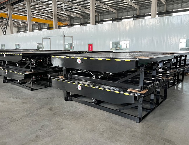
The installation of a fixed hydraulic dock leveler encompasses the entire process, from preliminary site surveys and foundation works to the hoisting of the main structure, hydraulic piping, electrical control systems, commissioning and final acceptance; it is suitable for steel or concrete loading bays.
Pre-installation
Measure the length, width and depth of the reserved pit for the loading bay, and verify the platform’s external dimensions and load capacity; if the pit dimensions deviate by more than 20 mm, the concrete must be chiselled away.
Measure the hydraulic dock leveler height: confirm the standard height of the loading bay to ensure it matches the platform’s lifting stroke; the pit depth must be sufficient to ensure the platform surface is flush with the loading bay when the platform is retracted.
Inspection of the foundation pit perimeter walls: Concrete structural strength must be C30 or higher; hollow brick walls must be reinforced with embedded steel plates; routing channels for hydraulic piping must be provided on the inner side of the foundation pit.
Confirmation of clearance at door openings: When the platform’s lip plate is extended, it must not obstruct roller shutters or crash barriers.
Excavation Works
Clear debris and loose material from the interior of the excavation pit, rinse it thoroughly, and allow any standing water to drain away.
Embedding of reinforcement steel plates on the four walls of the foundation pit: Embedded plates are laid at load-bearing points around the perimeter of the platform and secured using expansion bolts; the gap between the steel plates and the wall is grouted to ensure a solid seal.
Level the base of the foundation pit and lay a thin levelling layer of cement mortar to ensure the platform base sits flush with the ground, with no suspended support points.
Install pre-embedded bases for rubber bumpers at the front of the excavation, arranged symmetrically, to prevent lorries from colliding with the loading bay and platform at a later stage.
Reserve cable access holes: Drill holes in the side walls of the excavation for pipework and install plastic conduit to protect hydraulic hoses and cables from being crushed or worn.
Curing: Newly poured concrete foundations must be cured for at least 7 days; equipment may only be hoisted once the required strength has been achieved.
Lifting of the Platform Structure
Align the crane or forklift with the platform’s factory-fitted lifting eyes, lift steadily at four points, keep the platform surface level, and lower it slowly into the foundation pit.
Once in position, adjust the platform’s position front-to-back and side-to-side so that the gaps between the four edges of the platform surface and the foundation pit are uniform (10–15 mm clearance on each side).
Use a spirit level to check the levelness of the platform surface when retracted; the longitudinal and transverse levelness errors must be ≤2 mm/m.
Align the base of the hydraulic dock leveler with the embedded steel plates and secure it using full-penetration welding with thickened welding blocks; ensure that all base support points are firmly welded in place.
Once welding is complete, remove any welding slag and apply an anti-rust primer followed by a top coat to prevent the base from rusting.
Install safety support struts for maintenance: ensure the safety support clamps on both sides inside the platform are securely engaged; these will prop up the platform surface during maintenance to prevent accidental dropping and injury.
Fitting of Lip Plates, Anti-slip Side Panels and Impact-resistant Fittings
Install the front-end flip-up lip plate: align the lip plate’s pivot shaft with the hinged mount at the front of the platform, insert the pin and secure it with a retaining spring to ensure the lip plate can flip up and down without jamming.
The pins at both ends of the lip plate cylinder are connected to the lip plate bracket and the dock leveler base respectively; secure them with retaining springs to prevent the pins from falling out.
Install anti-slip side grilles on both sides of the platform, tightening the bolts evenly to fill the gaps on either side of the pit and prevent forklift wheels from becoming trapped.
Install large rubber bumpers symmetrically at the front of the loading bay, securing them with bolts and ensuring their height matches the chassis of the lorry’s body.
Fill the gaps around the perimeter of the platform with foam sealant and apply a weather-resistant sealant to the surface to prevent rainwater and silt from entering the pit.
Installation of Hydraulic Pumps and Oil Lines
Securing the hydraulic power unit: Install the hydraulic unit on the pre-fitted brackets on the side of the excavation pit, secure it with bolts, and ensure the unit remains level to facilitate future oil changes and maintenance.
High-pressure oil pipe layout:
Distinguish between the oil pipes for the main lifting cylinder and those for the lip plate cylinder. Route the pipes along the cable trays on the side walls of the excavation pit to prevent them from being crushed, kinked or trodden on.
Fit copper gaskets and seals to both ends of the hoses. Tighten the couplings by hand first, then secure them further with a spanner, applying moderate force to prevent stripping the threads.
Hose Securing: Secure the hoses with hose clamps at 50 cm intervals to prevent loosening and leakage caused by vibrations during equipment lifting and lowering.
Bleeding and filling the hydraulic system:
Open the filling port on the pump station and fill with the manufacturer’s specified 46# anti-wear hydraulic oil until the oil level reaches the upper or lower mark on the tank’s scale.
Cycle the lift mechanism 3–5 times in short, intermittent movements to repeatedly raise and lower the cylinder, thereby purging all air from the cylinder and piping until the movement is smooth and free of abnormal noises.
Inspect all joints: Leave the equipment to stand for 10 minutes and check for any oil seepage or dripping; if seepage is observed, replace the seals and retighten the joints.
Wiring of the Electronic Control System
Fixed electrical control box: Installed on the wall adjacent to the pump station at a height of 1.2–1.5 m, facing outwards to protect against rain.
Wiring separation specifications: 380 V power cables and hydraulic cylinder limit switch signal cables must be routed through separate conduits; high-voltage and low-voltage cables must not share the same conduit to prevent signal interference.
External Power Connection: Live, neutral and earth wires must be connected to the main circuit breaker; the earth wire must be reliably earthed to prevent electric leakage.
Equipment Wiring Connection:
Connect the three-phase power supply to the pump station motor;
Connect the limit switch signal wires for the up, down and lip plate lift positions;
Connect the emergency stop button control wires; install an external emergency stop switch on the outside of the control box.
Ensure all terminal blocks are securely fastened; wrap exposed copper wires with insulating tape; bundle any excess cables inside the box neatly; and seal the box door to prevent dust ingress.
Limit switch mounting: The upper and lower limit switches for lifting, as well as the lip plate position limit switch, are installed on the side brackets of the hydraulic cylinder. These are temporarily fixed in place, subject to fine-tuning during subsequent commissioning.
No-load Lifting Commissioning
Close the circuit and power on, then perform a momentary test to check the motor’s direction of rotation: press the ‘Up’ button and the worktop should rise smoothly; if it rotates in the opposite direction, swap any two of the three-phase live wires.
Up limit switch adjustment: Once the worktop has reached its maximum stroke, adjust the upper limit switch so that the motor stops automatically and the hydraulic cylinder does not reach its end stop.
Adjustment of the lower limit switch: Once the hydraulic dock leveler has lowered to a level with the loading bay, adjust the lower limit switch so that there is no height difference when the platform is retracted.
Adjustment of the lip plate flip mechanism: After the platform has risen, press the lip plate extension button; the lip plate should fold out completely and lie flat. When retracting, it should automatically flip upwards and lock into position at the limit switch without any jamming.
No-load cycle test: Perform 10 consecutive lifting and lowering cycles, observing throughout the entire process: no vibration, no abnormal noises, no vibration or displacement of hydraulic hoses, and no oil leakage.
Safety strut test: After raising the platform, engage the safety strut; release the hydraulic pressure; the platform remains stable and does not drop.
Load Testing and Commissioning
Test under 70% rated load: Place the corresponding counterweight on the forklift, drive it slowly onto the platform, and remain stationary for 5 minutes. Observe that the platform surface shows no significant deformation, the welds show no cracking, and the hydraulic cylinders do not lose pressure and sink.
Test under full rated load: Leave the platform fully loaded and stationary for 3 minutes; the platform surface must not sink by more than 3 mm to pass the test; If significant subsidence occurs, inspect the hydraulic circuit’s check valves and cylinder seals.
Forklift reciprocating traffic test: A fully loaded forklift repeatedly drives onto and off the platform; the lip plate must flip smoothly, the limit switches must trigger sensitively, and there must be no automatic slippage faults.
Emergency stop function test: When the emergency stop button is pressed during the lifting or lowering process, the equipment must immediately lose power and shut down, with all movements ceasing.
Sealing, Rust Prevention and Finishing Work
Apply a fresh coat of anti-rust paint to all welded joints and touch up any scuffs on the worktop to extend the service life of the anti-corrosion coating.
Seal all gaps in the foundation pit and pipe penetrations through the walls with sealant to prevent rainwater and dust from entering.
Tidy up excess oil hoses and cables, trim cable ties, and seal wall openings with conduit.
Clear oil stains and debris from inside the foundation pit, and unblock floor drains to ensure standing water can be drained away quickly.
All bolts and pins must be retightened to eliminate any risk of loosening caused by vibrations following hoisting and pressure testing.
Acceptance Criteria
Retracted position: The dock leveler is completely flush with the loading bay, with a height difference of ≤1 mm, and does not obstruct the passage of vehicles or forklift trucks.
Lifting operation: Lifting is smooth and shock-free; the lip plate tilts smoothly without jamming; there is no abnormal noise.
Hydraulic system: No oil leaks or seepage throughout operation; no noticeable sagging when stationary under full load.
Electrical system: All functions—raise, lower, lip plate and emergency stop—operate normally; limit switches are precise, preventing the platform from over-travelling or bottoming out.
Structural safety: The base is securely welded; impact blocks and safety struts are correctly fitted; the platform surface shows no deformation.
Drainage and corrosion protection: Drainage from the pit is unobstructed; the overall anti-rust coating is intact; seals are properly fitted.